Hybrid VTOL / Airborne radiation research
Atlas Falcon.
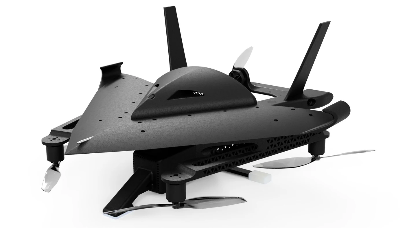
A research aircraft built to make airborne sensing more accessible.
Vertical takeoff, fixed-wing cruise, and a modular payload architecture in a roughly $1,200 USD platform. I own the engineering end to end, across the airframe, avionics, power, onboard computing, sensing, fabrication, and testing.
- endurance
- 46 min
- payload support
- Up to 1 kg
- total platform cost (USD)
- $1,200
- flight mass
- 2.5 kg
40 km estimated range; a 1.5 L internal bay supports modular integration.
First-author oral presentation · Health Physics Society 2026 · Travel grant recipient
Inside the aircraft
Select a chapter to look closer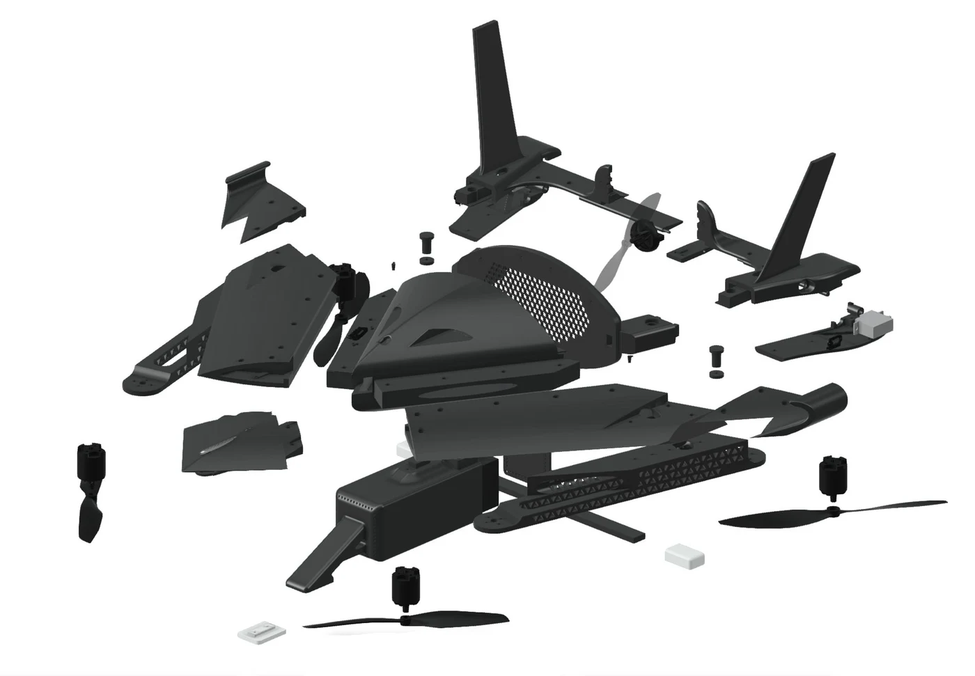
An aircraft designed around the payload.
A blended-wing body creates 1.5 L of internal volume in a transportable 49 × 50 cm platform. The airframe is built from carbon-fiber-reinforced nylon, with components that slide into place for assembly and replacement.
- Ownership
- I own the aircraft’s end-to-end engineering: airframe design, avionics and power architecture, embedded computing, sensor integration, fabrication, and testing.
- Reproducible fabrication
- 30 printed components, approximately 90 hours of unattended printing, and 50 hours of assembly. A desktop 3D printer and basic soldering skills replace specialized tooling.
- Structure informed by testing
- Brittle failure in PLA-Aero led to a move to PAHT-CF for stronger structural components.
Conference slides pp. 4–7; UROP poster, Methods & Discussion.
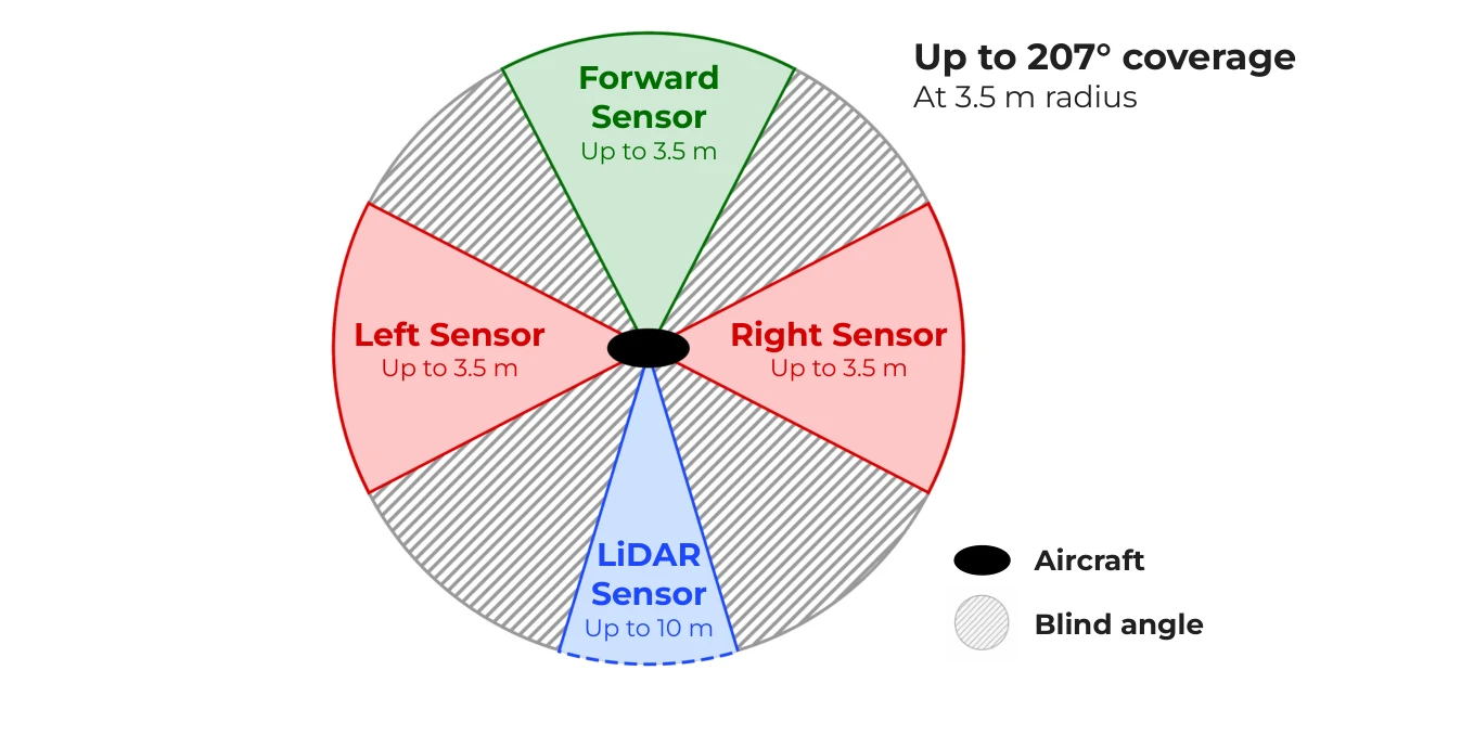
Wider awareness on a $60 sensor budget.
Overlapping time-of-flight and LiDAR measurements provide up to 207° of obstacle-detection coverage. The design combines inexpensive single-point sensors instead of relying on a costly multi-point scanner.
- Sensor architecture
- TFmini-S and VL53L1X distance sensors work alongside MAVLink position and velocity telemetry for obstacle reconstruction.
- Tested working envelope
- Frontal and lateral detection was validated over 0.5–3.5 m at ±2%. Coverage is directional, with a blind angle outside the sensors’ combined field of view.
- Integration, not a finished autonomy claim
- The sensing hardware is validated; improved obstacle avoidance and fully autonomous mapping remain in development.
Conference slides pp. 9, 12–13; UROP poster, Results & Methods.
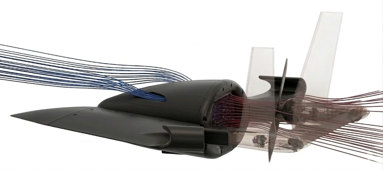
Schematic animation over the original airframe study. Flow direction is illustrative; color and speed do not represent calculated values.
Battery cooling detail
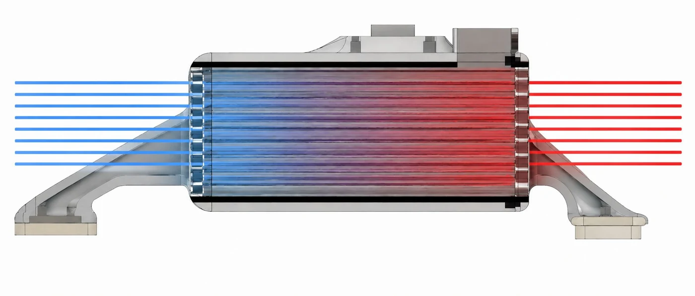
The airframe is part of the cooling system.
Cooling is integrated into the aircraft itself. The airframe routes incoming air through the onboard electronics toward the rear propulsion system, using propeller-induced airflow to remove heat from the fuselage.
- Airframe, propulsion, and electronics
- The intake, internal airflow path, and rear exhaust work together. Propulsion creates the airflow; the airframe directs it through the systems that need cooling, without dedicated fans.
- Measured thermal effect
- Propeller-driven airflow reduced electronics temperatures by 10–12°C and battery temperatures by 3–5°C under sustained load.
- Thermal evidence
- Under a Prime95 stress test, the SBC reached 84.1°C without propeller airflow and 72.0°C with it after 60 seconds. A separate battery stress test at 90% load capacity showed a 3.4 K difference in inferred temperature after 300 seconds.
Resume; conference slides pp. 5, 8; UROP poster, Results.
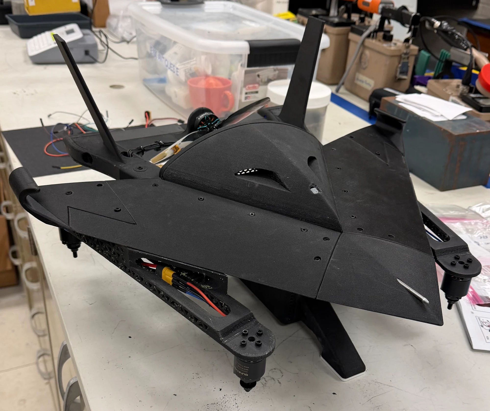
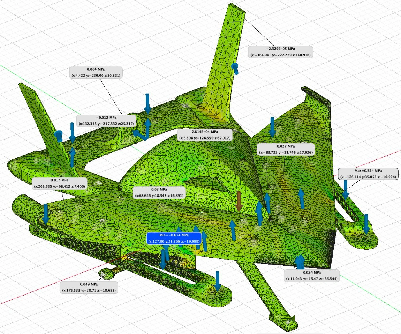
Validated through analysis and physical testing.
Atlas Falcon has been manufactured, assembled, and flight-tested. Structural analysis, load testing, thermal measurements, and propulsion testing support the platform’s development.
- Measured versus modeled
- FEA predicted a 12 kg load tolerance. Physical testing measured failure at 8.0 kg, distinguishing the modeled capacity from the experimental failure load.
- Presented to the research community
- First-author oral presentation at the 2026 Health Physics Society Annual Meeting, with a travel grant. Research conducted with Kimberlee J. Kearfott at the University of Michigan.
- Next integration steps
- Planned work includes radiation-detector integration, improved obstacle-avoidance software, fully autonomous mapping, and a web-based mission interface.
Resume; conference slides pp. 7, 10, 13–14; UROP poster.
From design values to measured results
Explore the test dataCruise propulsion at 14.8 V
- Nominal
- 80gf
- Experimental
- 47.1gf
Nominal manufacturer values versus experimental thrust. The measured curve remains below nominal at each supplied throttle setting.
View exact readings
| Throttle (%) | Nominal (gf) | Experimental (gf) |
|---|---|---|
| 10 | 80 | 47.1 |
| 20 | 220 | 138.2 |
| 30 | 420 | 305.8 |
| 40 | 650 | 515.4 |
| 50 | 756 | 739.1 |
| 60 | 1100 | 932 |
| 70 | 1450 | 1142.8 |
| 80 | 1750 | 1335.7 |
| 90 | 2000 | 1498.6 |
| 100 | 2158 | 1623.9 |
Curves connect measured samples without smoothing or extrapolation. The 5–60 s thermal test tracks the SBC; the 15–300 s test tracks inferred battery temperature.
A mission from takeoff to touchdown.
Vertical departure
Takeoff
Leave the ground vertically without a runway.
Mission concept from conference slides, p. 11. The diagram shows the mode sequence, without an altitude or distance scale. Fully autonomous radiation mapping is a planned integration step.